| |
Heat Shrink Terminations Systems |
(Single and triple core Power Cables
up to 36 kV)
|
| |
|
 Ikebana Heat Shrink Terminations and Joints Brochure
(Specifications and the product dimensions given in this brochure are subject to change without notice.
Please refer to the latest version of the drawings and specification-sheets on the Ikebana web site,
or contact our office in Thailand.)
|
| |
Heat Shrink Terminations System upto 36kV |
| |
| Governing
Standards: |
| DIN VDE 0278/ CENELEC "POWER CABLE ACCESSORIES WITH RATED VOLTAGE UP TO 36 kV (Um = 42 kV)", IEEE 48-1990: HIGH VOLTAGE ALTERNATING-CURRENT CABLE TERMINATIONS. |
| |
| Type Testing |
| Ikebana MV Termination system is type tested as per DIN VDE 0278 / CENELEC standards in independent recognized laboratories. The type test reports will be available on request. |
| |
| Parts of the
Termination System: |
| |
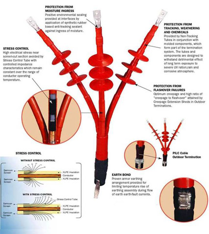
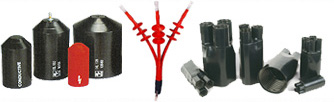
| 1. Heat Shrinkable non Tracking Tube: NTT (Red) |
| Non tracking tube (red) is used as an external protective covering for the core for both indoor and outdoor applications. Properties of this tube are high insulation, non tracking, erosion resistant, weather proof and flame retardant. Minimum length of the non tracking tube depends on the system voltage and whether the application is indoor or outdoor. Please refer to the engineering drawing for details. |
| |
| 2. Heat Shrinkable Stress Control Tube: SCT (Black) |
| Stress control tube (black) is used to control the high electrical stress present at the end of the semi-con screen of the cable. This tube has a combination of resistive and capacitive characteristics which, when applied to the end of the semi-con screen of the cable, give relief to the electrical stress, by stress grading. The minimum lengths of the stress control tube necessary for effective stress control are 130 MM for 12 kV, 190 MM for 24 kV and 260 MM for 36 kV. |
| |
| 3. Heat Shrinkable LUG Seal |
| HV lug seal is made from the same material as the non tracking tube and is coated internally with the red sealant. Lug seal protects the interface between the termination lug and the cable core covered with the non tracking HV tube. |
| |
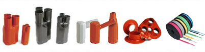
| 4. Heat Shrink MV Breakout |
| MV breakouts are used to provide insulation, binding force and sealing over the crutch of three core cables at the branching point. They are coated internally with waterproof, non-tracking, butyl rubber based red sealant mastic. |
| |
| 5. Heat Shrink HV Sheds |
| HV sheds are used to extend the creepage path. The properties of the HV Sheds are electrical insulation, non tracking, erosion resistant, weather proof and flame retardant. HV Sheds are internally coated with waterproof, non-tracking, butyl rubber based red sealant mastic. The minimum number of sheds designed to be used in the termination system depends on system voltage and whether the application is indoor or outdoor. Please refer to the engineering drawing. |
| |
| 6. Conductive Paint / Stress Grading Mastic |
| Conductive paint / Stress grading mastic is applied around the step formed at the screen-cut point i.e. at end of the semi-con screen and start of the XLPE insulation of the cable, to render the air entrapped at the step discharge free. Use of either conductive paint or stress grading mastic in the termination, depends on the respective end users. Terminations of both types are available and have separate installation procedures. |
| |
| 7. Red Sealant |
| Red sealant is applied around the base of the terminal lug where it is crimped to the cable conductor. The red sealant acts as a filler and insulating material to fill in the step formed at the end of conductor insulation. It forms a waterproof seal at the end of the termination, which is essential for the long service life of the termination. The red sealant is made from butyl rubber based mastic and has good non-tracking properties. |
| |
| 8. Discharge Supression Compound |
| Cuts and scratches on the XLPE insulation may cause electric discharge under the stress control tube. Application of a thin layer of silicone based discharge suppression compound will make it free of partial discharge. |
| |
| 9. Earth Bond |
| The earth bond arrangement consists of a metallic ring, hose clips and tinned copper braid attached to the copper tape screen of each core and armour of the cable at the base of the termination. This proven armour earthing arrangement provides sound electrical contacts at armour bonding points and avoid excessive temperature rise during earth faults. |